
Cubejam is an interactive artwork that allows young people to make music. Its first prototype was deployed at the South Coast Children’s Festival 2011.
It is inspired by the Reactable tangible music interface. It uses the same open source fiducial tracking engine: reacTIVision. As such Cubejam itself is also open source. I write my code in the vvvv toolkit, which is not open source but free for non-commerical use. You can download my vvvv patches in the extended at the bottom of this post.
Cubejam Prototype 2011 from Toby Knyvett on Vimeo.
Working with kids
The scale and format of Cubejam is designed to encourage collaboration and play between children of various ages. Over three days of running the prototype we tried several different forms of play with the cubes. We started with groups of 8 or 9 doing 10 minute workshops where I would mediate. This structured approach was the best way to manage the lines of children at the start.
Eventually the flow of children slowed down and the kids would come into the space individually or in small groups. Rather than instruct each new child I would let them learn from those who were already in the space. This was far more successful in terms of leading to scenarios with genuine experimentation and play. If I introduced the concept they expected me to explain how it was’meant to be used and what they should be making with it. If another child was the first point of contact they would typically collaborate and experiment together. An adult was still required from time to time, mostly to prevent the cubes being crushed or kicked, but generally the children would guide themselves.
In terms of age groups I was surprised to find that older kids weren’t necessarily faster to learn how the cubes worked. At all ages there were simply some children who immediately made a connection between the surfaces of the cubes and different sounds.
It’s an open question as to whether the kids even had to make that connection for cubejam to be successful .Some kids were clearly only making a connection between placing the cube on the plinth and the visual response from the projector. However they were still playing, collaborating and experimenting.
The only group for whom it didn’t work was kids who simply wanted to be physical with the cubes, occasionally with some amount of violence. This behaviour seemed to be more about the reaction of other children in the room. Still we learnt that the finished cubes need to be a bit hardier.
 How does it work?
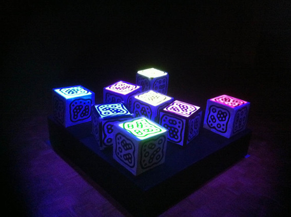
The basic idea is that any cube placed on the plinth will ‘light up’ and generate music. When it’s flipped over onto another side a different, but related, sound is heard. For instance one cube might generates kick drum sounds in different patterns, whilst another does snares or melodies.
The technical challenges are:
* Work out which cubes are on the plinth, and which side up they are.
* Play back the sounds in sync with each other regardless of the timing of actual changes to cubes
*Allow the cubes to ‘light up’ and have a visual response
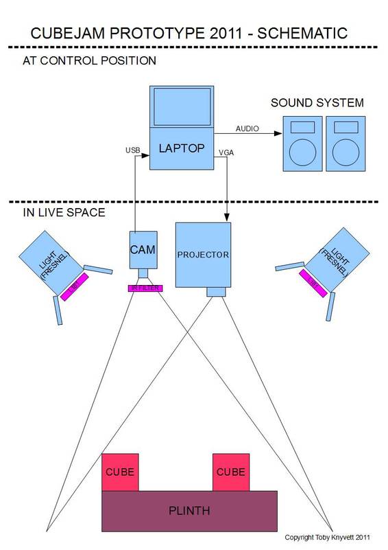
Hardware:
PC laptop
Projector – 4000 lumen Panasonic
Camera – Modified PS3Eye USB cam
8 x Fiducial cubes – cardboard attached to a canvas frame.
Sound System
Hardware for rigging projector and camera overhead.
Tracking the cubes
In order to allow the computer to understand which cubes are on the plinth I turned to fiducial tracking. A fiducial is a unique visual marker that can be picked up from a video stream. The reacTIVision system I used comes with it’s own set of fiducial markers. Potentially a fiducial marker could be anything, including an image of a drum etc… however for CPU performance reasons the abstract markers that come with reacTIVision are optimal. For each marker that can be seen reacTIVision returns an ID number, X and Y position and rotation. (Note that this rotation is the 2d rotation of the visible marker in relation to the camera, not the 3d rotation of the whole cube. We work out the orientation of the whole cube by the ID of the fiducial which is facing the camera)
There are some limitations with fiducials. The first is that each fiducial must be appear at a minimum size within the camera frame in order to be recognised. In the real world this means the further away your camera is (or the further zoomed out it is) the bigger your physical fiducials have to be. After several trials I settled on a 1.5m x 1.5m tracking area and aprox 450mm cubes. This was the best combination given the camera lens, projector lens and height to roof I was working with.
The other limitation with fiducials is that you need to have consistent brightness/contrast over the entire camera area . The algorithm will only find markers within a certain contrast range, if the markers change contrast, say by going in and out of shadowy lighting, you will lose them. Because I was going to have children and adults standing on all sides of the plinth and casting shadows I knew this would be challenging. I also knew from early experiments I would have a problem with the projector lighting the cubes – as soon as a cube was tracked it would be lit by the projector, appear brighter to the camera, and then potentially not be tracked because of the increased brightness. The solution was to track in infrared. It just so happens that digital projectors cast very little infrared light. Conventional theatre lights also make great infrared lights so I used four 1000w fresnels around the plinth. I then put an infrared filter (a visible light blocking filter) in front of the camera. The angle had to be just right to ensure there was no glare but that minimum shadows were cast from the crowd. It took some fiddling but in the end was pretty stable.
I used a PS3 Eye camera with custom M12 Lens from Peau Productions. I used my own IR filter made of Lee 181 ‘congo blue’ coulour filter folded over several times. I put this same gel in the theatre lights so they cast a minimum of visible light and made the glow effect more dramatic. The PS3 cam is USB and because it was in the roof I needed some ‘active’ 10m USB extensions to get it running. Without the little active booster the camera can only be 4 or 5 metres from the computer using conventional cables. I used the PC drivers from Code Labs. Probably the best feature of the PS3Eye vs an off the shelf webcam or a capture card is it has extremely low latency. The time between real life and the image ‘appearing’ in the computer is the lowest of any consumer cam I’ve used.
Playback and control
I used Renoise for audio playback. It’s what’s known in the music software world as a tracker. It allows very precise control of when and what sound is played. It’s a very well written piece of
software and uses little CPU power to run a rock solid playback engine. This is what allowed the sound to stay in sync no matter how much resources were required by the video tracking and projection side of things. Within Renoise I created six tracks for each playback cube – one for each side. I then set it up to receive commands via OSC that would enable or disable playback of each track.Each group of six tracks was routed through a virtual auxiliary. By controlling effects placed over each auxiliary I could control which playback cubes were affected by which effects cubes.
I used vvvv for everything else. It comes with a version of the reacTIVision library so I could get my ID, X, Y and rotation values directly in vvvv. From there it sent control data to renoise via OSC and Midi. It also generated the vision that was sent to the projector. You can download the patch I created at the bottom of this post.
Visual Feedback
Visual feedback was achieved by projecting onto the cubes from above. Because I knew where they were, their rotations and how big they should be in relation to the camera I could simply project coloured squares back down onto the cubes. This also helped to differentiate them once they were on the plinth.
I wanted each cube to ‘flash’ as each sound was triggered. This meant getting some data back from Renoise and into vvvv. Basically I needed the data that drove the volume meters for each track in renoise. This is unfortunately not a native function in renoise. However danoise, a user on the renoise forums, helped me out by creating a VST plugin effect that took amplitude and pushed out as a midi controller value.
The only tricky part here was rigging the projector above and focusing it to have the same ‘view’ as the camera. It would also be possible to use a mirror if you had a projector that could only be rigged on near flat angles, but it would only making focusing more difficult.
Lastly keep in mind with both the projector and camera focus that from above you need to hit an area slightly bigger than the plinth. Cubes near the edges will appear to have their own top edges outside the borders of the plinth.
 The future
There are a whole bunch of places I want cubejam to go. The first thing is that I need some new cubes. Some of the most common feedback that it would be incredibly useful if the cubes could be meaningfully differentiated before they are placed on the plinth and light up. However due to the nature of the fiducials I can’t just print any symbol I like on them. I may be able to solve this with some kind of infrared only ink with which I could print a fiducial, and then a visible spectrum only ink with which to print a real image. I also may be able to do it with little symbols around the edge of the cube or similar.
Another solution might be for each cubes to have a different tactile response so you can ‘feel’ the nature of the instrument. Perhaps even braille descriptions on each face?